A robot drives down a corridor and its camera sees only a blank wall. What is visual inertial odometry doing then? It estimates the robot’s pose and velocity by fusing camera and IMU data, so the IMU carries the motion estimate through the gap.
VIO is one navigation building block for indoor autonomous robots. It tracks motion only. It does not build a full map, and it does not eliminate drift, which is the main misunderstanding this guide corrects.
What visual inertial odometry estimates
Visual inertial odometry (VIO) is the process of estimating the state, meaning the pose and velocity, of an agent using cameras and inertial measurement units, as defined in a survey of the field. In that setup the camera and IMU are rigidly attached to each other. They output visual and inertial measurements at different rates, and the estimator has to reconcile the two streams.
The payoff is metric motion. The University of Zurich’s robotics group notes that metric 6 degree of freedom state estimation is possible with a single camera and an IMU. A camera alone recovers the trajectory only up to a scale factor.
| Property | Camera | IMU | Planning use |
|---|---|---|---|
| Output rate | Limited, about 100 Hz | High, about 1,000 Hz | Let the IMU fill the time between image frames. |
| Scene dependence | Struggles with low texture, high-speed motion and motion blur | Scene-independent, so unaffected by those difficulties | Expect the IMU to dominate when the image is poor. |
| Weak spot | Loses reliable tracking in poor scenes | Biases make drift accumulate quickly; poor signal-to-noise ratio at low accelerations and angular velocities | Expect vision to correct the IMU, not the reverse. |
| Metric scale | Monocular motion known only up to an unknown metric scale | Makes metric scale and gravity observable | One camera plus one IMU is enough to anchor scale. |
The figures and limitations in this table come from the VIO survey on arXiv.
Why a camera and an IMU belong together
The two sensors fail in different ways, so each covers the other’s weakness. That is the whole case for combining them.
An IMU alone drifts
A common misunderstanding is that a good IMU could navigate by itself. Because of sensor biases, the motion estimated from an IMU alone tends to accumulate drift quickly, according to the survey. The IMU also suffers from poor signal-to-noise ratio at low accelerations and low angular velocities, so slow, smooth motion is hard for it to read.
A camera alone loses scale and some scenes
The reverse assumption is that a camera is enough. A monocular camera measures the geometry of the scene and its own motion only up to an unknown metric scale. It is also not robust to scenes with low texture or to high-speed motion that causes motion blur. The IMU is unaffected by both problems, which is why the pairing works.
Stereo is optional for scale
Many people assume a stereo camera is required to get real-world units. It is a common choice, and the survey shows a stereo visual-inertial sensor as a typical suite. But the metric scale comes from the IMU, so a single camera and an IMU can already deliver metric state estimates. Stereo visual odometry remains a sensible hardware option when you want the camera to contribute more on its own, and it does not remove the need to handle IMU biases.
Tightly coupled and loosely coupled fusion
How the two sensors are fused matters as much as which sensors are used. The survey separates the approaches by when the data are combined.
- Loosely coupled: visual and inertial measurements are processed separately, producing two independent motion estimates that are fused afterwards. This design cannot correct drift in the vision-only estimator.
- Tightly coupled: the final output is computed directly from the raw camera and IMU measurements. The survey states that tightly coupled approaches are more accurate than loosely coupled ones.
For a robot that must keep tracking through poor imagery, tight coupling is the better fit, since the IMU can help the visual side directly rather than only being averaged in at the end.
How the IMU helps feature tracking
Feature tracking follows image points from frame to frame. Integrating the IMU can predict where the 2D feature locations will appear in the next frame, which makes tracking easier. Corner points found with detectors such as FAST and ORB are the standard features, according to a VIO overview, while line features can assist in low-texture scenes.
What causes VIO drift
VIO drift is the slow growth of error in the estimated trajectory. It does not have a single cause, and fusion reduces it without removing it.
- IMU biases: accelerometer and gyroscope biases are necessary to compute the true angular velocity and acceleration from raw measurements, so VIO estimates them as part of its state. Left uncorrected, they cause fast drift.
- Cheap sensor errors: for low-cost IMUs a simple bias-and-noise model can be oversimplified, and additional errors from scale factors and axis misalignment come into play.
- Scale drift: a VIO overview lists scale drift among the ongoing challenges, along with degeneracy under planar or pure-rotation motion.
- Weak coupling: a loosely coupled design leaves vision-only drift uncorrected, as noted above.
Practical direction follows from this. Choose tight coupling, expect to estimate biases continuously, and treat any remaining drift as something a larger system must handle. Recognising revisited places is one such correction, covered in what is loop closure in slam.
Where VIO fails indoors
Indoor failures mostly come from the visual side. Research from the University of Zurich lists low texture and severe motion blur among the conditions that degrade visual SLAM, and the same difficulties carry over to the camera in a VIO rig.
Blank walls and low texture
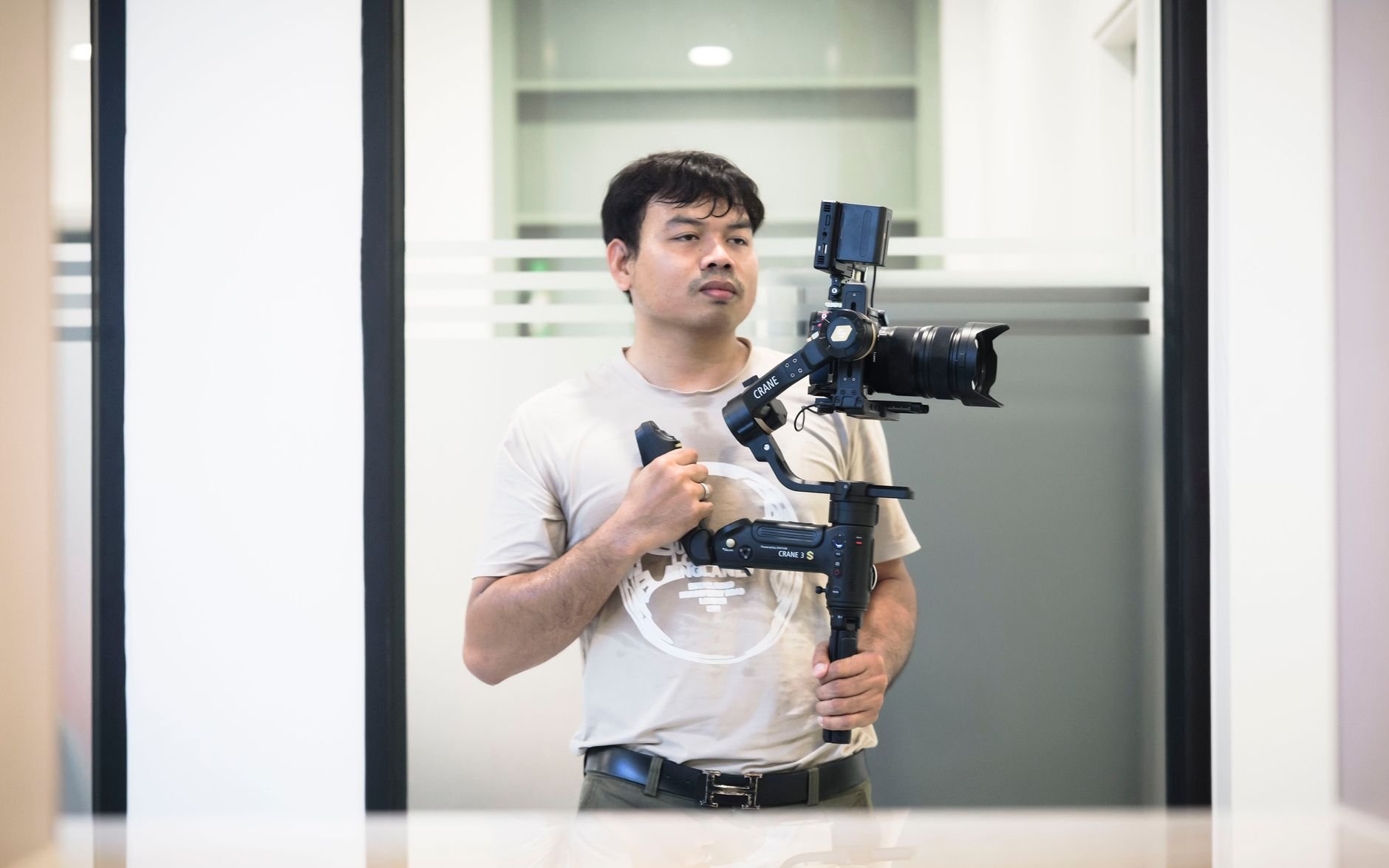
A plain wall gives the tracker nothing to follow. The IMU can bridge short gaps because it is scene-independent, but its drift grows quickly, so a long featureless stretch is where the estimate degrades most.
Mixed corridors
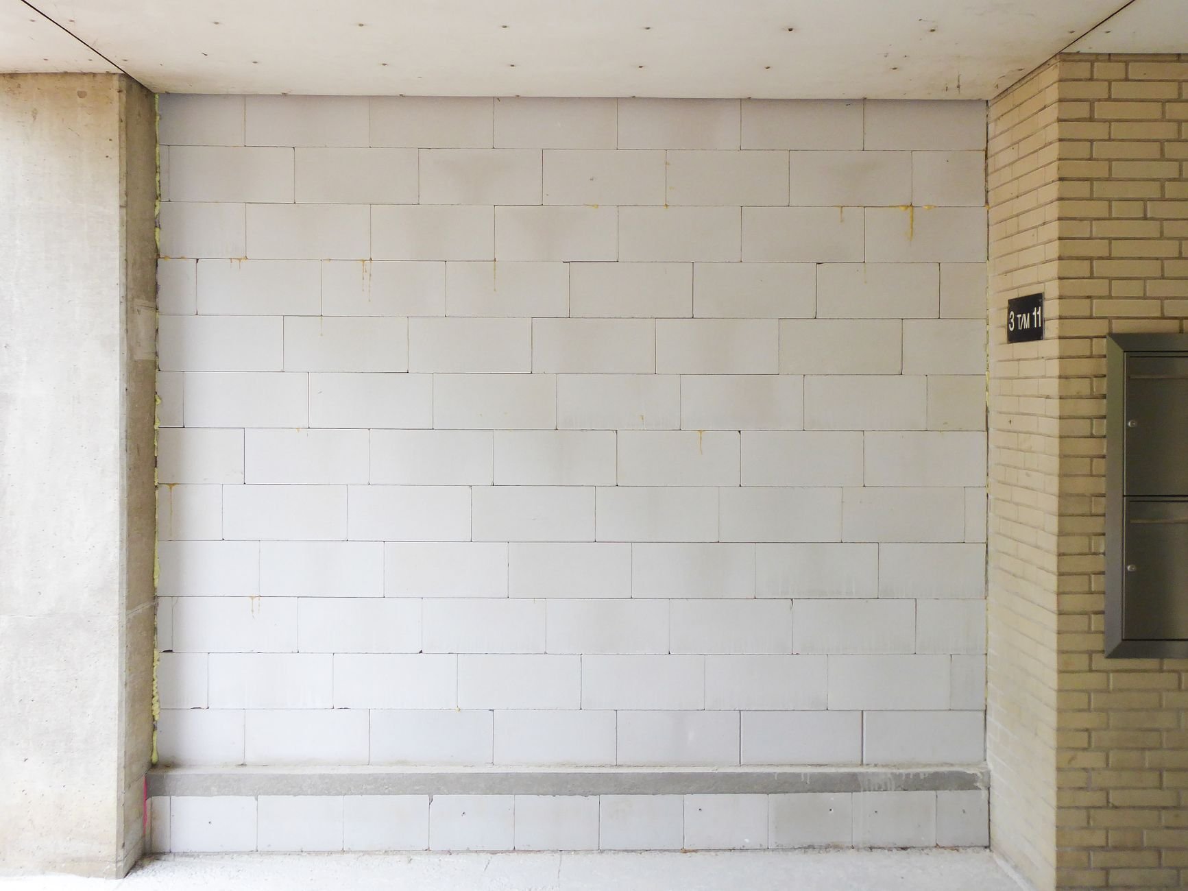
Real buildings mix textured and bare surfaces. A scene with patterned elements keeps the camera useful, while the bare sections shift the burden to the IMU. Line features can help in low-texture scenes, according to the overview, but a robot route that crosses long bare stretches still needs a plan for them.
Fast motion
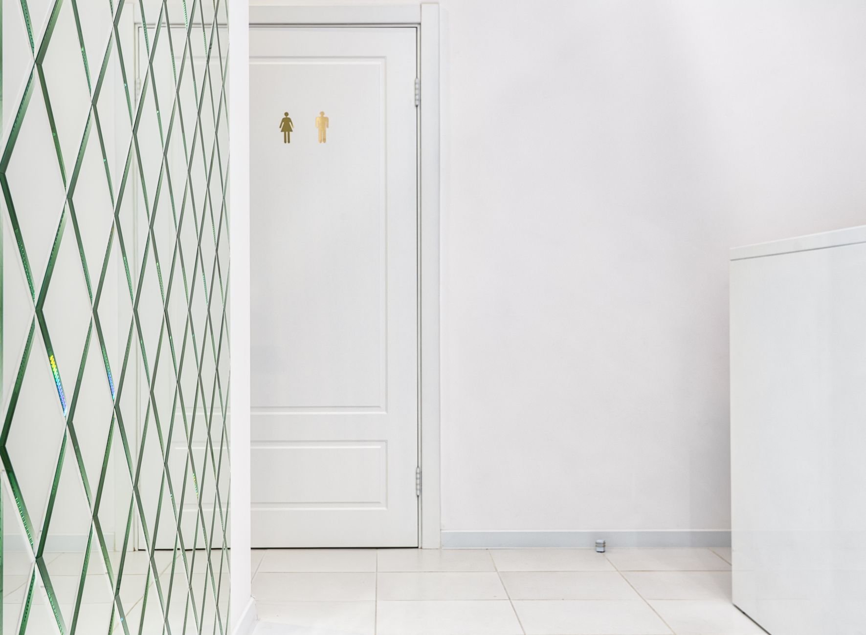
Quick turns blur the image, and blurred frames defeat feature tracking. This is the situation where the IMU’s high output rate helps most, since it keeps measuring even when the images are unusable.
Open-source systems and benchmarks
VINS-Mono is a widely named open-source option. A VIO overview groups it with OKVIS as a fixed-lag smoothing system, which jointly optimises over a recent window of states and marginalises old ones. Its name signals a monocular camera plus an IMU, and open-source VIO projects such as this GitHub implementation likewise estimate position and orientation by fusing a camera and an IMU, with VINS-Mono cited as a reference.
Researchers validate VIO on public datasets including the EuRoC MAV dataset, KITTI, TUM-VI and KAIST. Run a candidate system on a recorded dataset before trusting it on your own robot, because a dataset shows how a method behaves with known sensors and conditions.
Collecting your own data
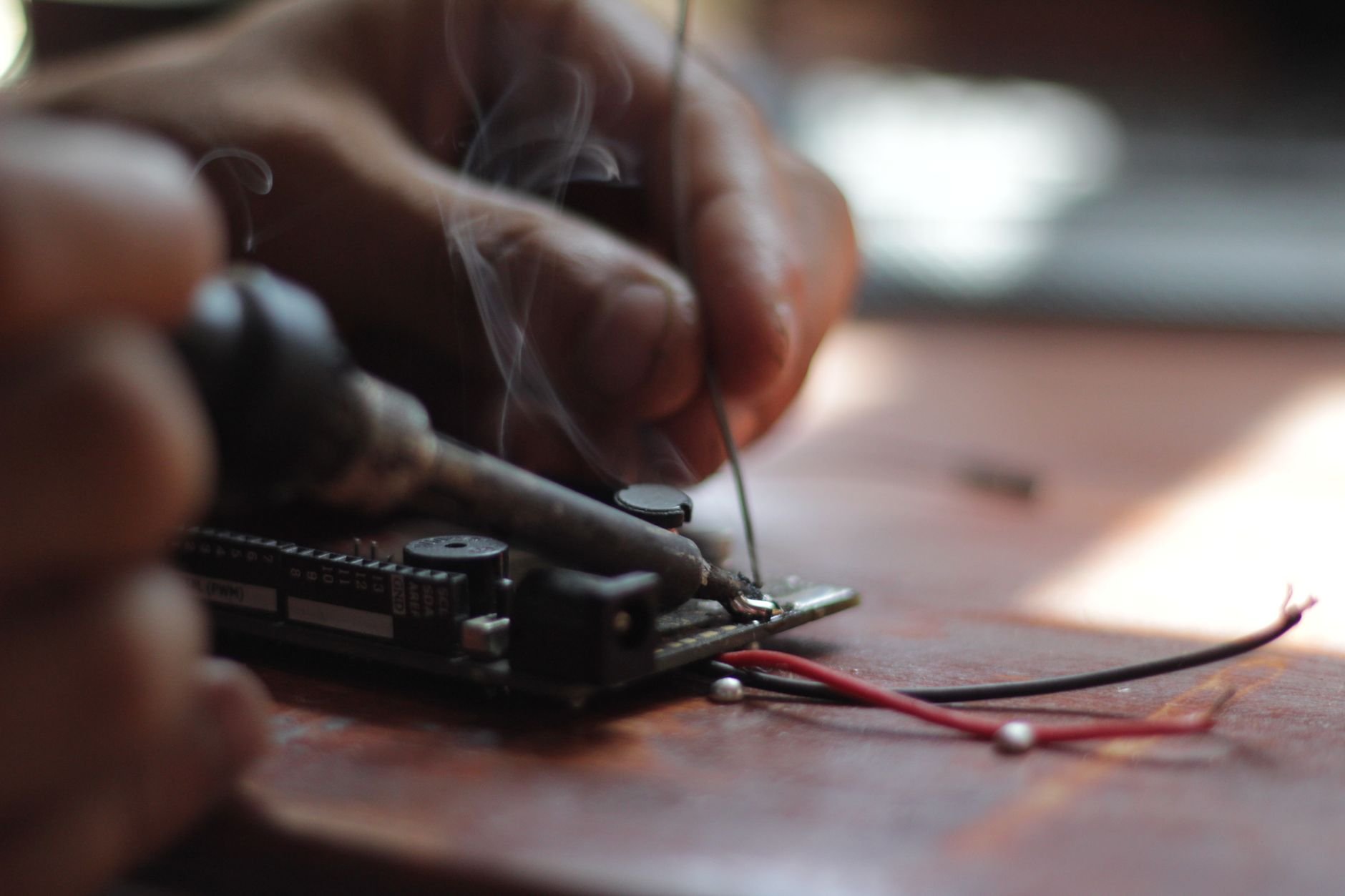
Data for VIO comes from a rigidly mounted camera and IMU moved through the environment, often on a handheld rig. Keeping the sensors fixed relative to each other matters because the estimator assumes a rigid attachment. If you are still choosing the vehicle that will carry such a rig, amr vs agv compares the two platform types.
Frequently asked questions
| Question | Answer |
|---|---|
| How is VIO accuracy reported? | Common metrics include Absolute Trajectory Error (ATE), Relative Pose Error (RPE), RMSE and drift percentage, according to a VIO overview. |
| Does poor lighting affect VIO? | Yes. Poor illumination is among the conditions that degrade visual methods, and fusion with an IMU is used to address visual ambiguity in low light, though IMU drift still limits how long it can compensate. |
| What does VIO output? | The state of the agent, meaning its pose and velocity, as defined in the survey. |